Views: 0 Author: Site Editor Publish Time: 2020-09-28 Origin: Site


Incremental encoder sensors provide some circuit output signal on a single transmission line.
the sensor should be connected to one controller.
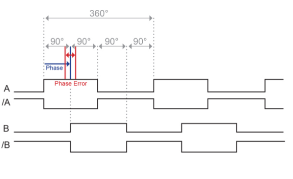
An incremental encoder has at least 1 output signal “A” phase or typically 2 output signals, called “A” +“B” phases. These 2 signals are set up with a 90° offset, which is required for the detection of the encoder’s rotation. By turning the encoder clockwise, the “A” pulse is rising 90° ahead of the “B” pulse, in the same way, the “B” pulse is rising ahead of the “A” pulse when turning the shaft direction in counterclockwise.
Besides,some incremental encoders output a “Z” phase signal. Once every rotation, this Z phase signal is rising for typically 90°, on the exact same position. This can be used as a dective of the accurate reference point.
Some other incremental encoders also have additional differential signals, called “A-”, “/B-” and “Z-”. These signals are inverted of “A”, “B” and “Z” signals. Controllers can compare each pair (“A” must be equal to inverted “A-”) to make sure that there is no error during the signal transmission.
In common,the transmission sensitivity is improved by transmitting the differential signals through a twisted pair cable.
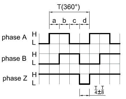
Some typical pulse diagram of incremental encoder
Pulses per revolution (PPR):
An incremental rotary encoder outputs a certain amount of Pulses per Revolution. The higher this PPR number, the smaller the angle between each pulse. This PPR number is fixed for ordinary incremental encoders.
Today most incremental encoders have a Push-Pull (which is also called HTL) or RS422 (TTL) output driver, these have replaced most of the older output circuits like Open Collector NPN, Open Collector PNP, Voltage Output.
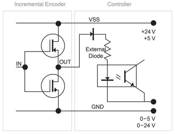
A) Push-Pull Signal Output (HTL)
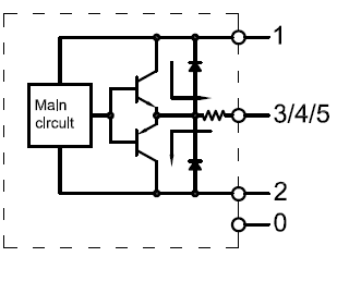
Push-Pull (HTL) circuits, also known as the Totem Pole circuits, provide a signal level which corresponds to the applied supply voltage. The supply voltage typically ranges from 8 to 30 VDC,or a wide range from 5-30VDC .
With proper connections you can use the Push Pull interface to replace true open collector circuits by using an external diode connected in a way to limit the direction of the current.
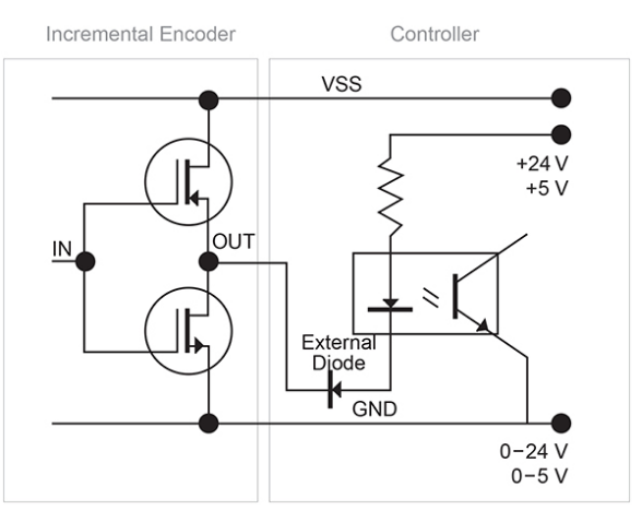
B) RS422 Signal Output (TTL)
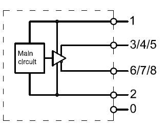
RS422 (TTL) circuits provide a constant 5 V signal level that is not dependent on the supply voltage. Two supply voltage ranges can be selected: From 4.75 to 5.5 VDC (can be used to replace open collector output drivers) or from 5 to 30 VDC. Using differential signals the output fully complies to the RS422 standard.
The differential outputs have the highest frequency response capability and the best noise immunity.
To ensure this the receiver should also be a differential circuit.
the Replacement curver of some oldr Output Drivers
1) PNP open collector replacement (Current source)
2) NPN open collector replacement (Current Sink)
Voltage Output Levels:
A logic gate interprets certain input voltages as high (logic 1) or low (logic 0).
TTL (transistor-transistor-logic): A signal above 2 V is interpreted as logic 1 and a signal less than 0.8 V is interpreted as logic 0. The output voltage ranges between 0-5 V.
HTL (high-threshold-logic): A signal above 3 V is a logic 1 and a signal less than 1 V is a logic 0. The high output signal level is dependent from the supply voltage. Because of the higher voltage difference between logic 0 and 1, the HTL logic is more immune to interference and more resistant against electrical noise.
| Logic | Signal Level | Supply Voltage | Output Voltage |
| TTL | High | 5-30 V | min 3 V |
| Low | 5-30 V | max 0.5 V | |
| HTL | High | 5-30 V | min 3 V |
| 8-30 V | min Supply Voltage - 3 V | ||
| Low | 5-30 V | max 0.5 V |
Electrical and Mechanical Degree:
Mechanical degree is the actual rotation of the shaft in degrees. Electrical degree is used for electrical signals. The required time for completing one alternating voltage/current cycle is defined as 360 electrical degrees (el°).
For incremental encoders, one cycle is equal to one complete pulse. With a given PPR the electrical degree can be converted to mechanical degree for any incremental encoder.
Quadrature:
Every 90 el° the incremental encoder outputs a rising or falling edge on the “A” or “B” output that can be interpreted as a count. If an encoder outputs 1000 PPR, a counter can interpret 4000 counts (4 counts each pulse).
Phase Angle:
The phase angle states the length between 2 edges, given in el°. This parameter is typically specified with a defined constant phase angle value and phase angle error (also called quadrature error).
Accuracy :
The accuracy is the phase angle error as an absolute value given in (mechanical) degrees.
An incremental encoder outputs a defined amount of pulses per revolution, so that every pulse is expected to be on a defined mechanical position. The maximum deviation between this ideal position and the actual position is called integral non linearity. accuracy is an important value if the incremental encoder is used for positioning tasks.
Duty Cycle:
The duty cycle describes the ratio between “high” time to “low” time of an incremental encoder. Typically this ratio is 50/50, which is equivalent to 180 el° high and 180 el° low.
The performance ofc incremental encoders increases with higher PPR settings and higher rotation speeds (RPM). This is in contrast to optical encoders where the performance decreases. The accuracy that are stated in our datasheets are worst case values, a better performance can be expected for higher PPR and RPM.
Frequency Response:
This is the maximum frequency that the encoder is able to output via the output lines.
For example, the frequency of a 1024 PPR encoder that rotates at 1757 RPM is 300K Hz (30,000*1024/60s).
If you still have any some doubts on the theory of incremental encoder, pls contact our techician to get more support.
email : heng@shhxgd.cn